Virtual sensors
Virtual sensors
Virtual sensors allow you to process telemetry data more effectively. By mapping board voltage, they can help you calculate engine hours based on set conditions and values. Additionally, they allow you to convert multiple data points from different sensors connected to a device into easier-to-understand indicators such as "hot," "cold," "open" and "closed," regardless of the device's manufacturer or model. This opens up new possibilities for monitoring, tracking and predicting the performance of complex technologies.
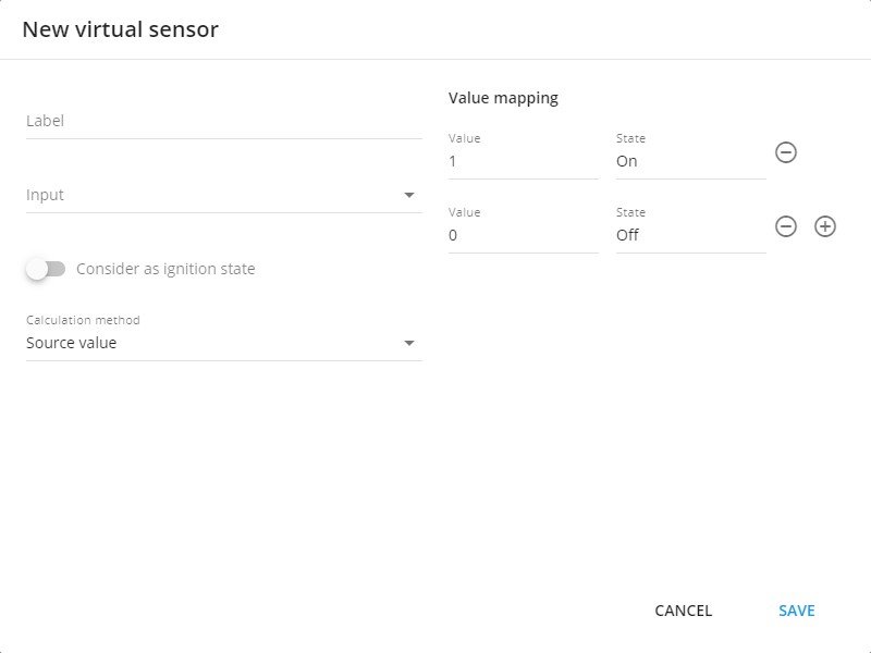
Virtual sensor interface
How to create a virtual sensor
Virtual sensor can be created via the “Sensors and Buttons” portlet located in the Devices and settings tab:
Enter the devices and settings section.
Select a GPS tracker.
Click “+”.
Select the “Virtual sensor option”.
Every device may have up to 100 virtual sensors.
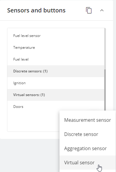
Virtual sensor adding in sensors and buttons portlet
The next steps depend on the use case that should be solved via the Virtual Sensor. Below you can find examples and instructions for different calculation methods.
Calculation methods
Virtual sensors have three different calculation types:
Value in range.
Source value.
Bit index.
All values for virtual sensors must match the form in which they are received from the device. All states are your definitions for these values.
Here, we describe how different calculation methods work. Click on the calculation method name to expand.
Value in range
This type of virtual sensor helps our customers to keep important parameters such as virtual ignition, temperature, humidity, and fuel level within a specified range.
Here's how it works:
if the sensor value is inside specified boundaries, it is 1 for the platform. And 1 is equal to your A value.
if the sensor value is outside of these frames the virtual sensor’s value is 0 for the platform. And 0 equals to your B value.
Example on virtual ignition
If you don't have an ignition input or your device is already running at full capacity, you can use a Virtual Ignition Tool to detect the ignition state. The onboard voltage of the car will increase significantly when the engine is switched on, allowing the voltage threshold to be used as an indicator of whether or not the engine is running. Generally, the board voltage should exceed 13.2 V to indicate that the engine is functioning.
To create this sensor:
Start by giving it a name.
Set the input to Board Voltage, or any other sensor if needed.
Enable “Considering as ignition state” in the settings.
Choose “Value in range” as the calculation method.
Specify a minimum range value, such as 13.2 V. Maximum isn’t necessary there since the Board Voltage can vary with ignition on.
Finally, set the 0 and 1 states meaning - usually this is On and Off respectively
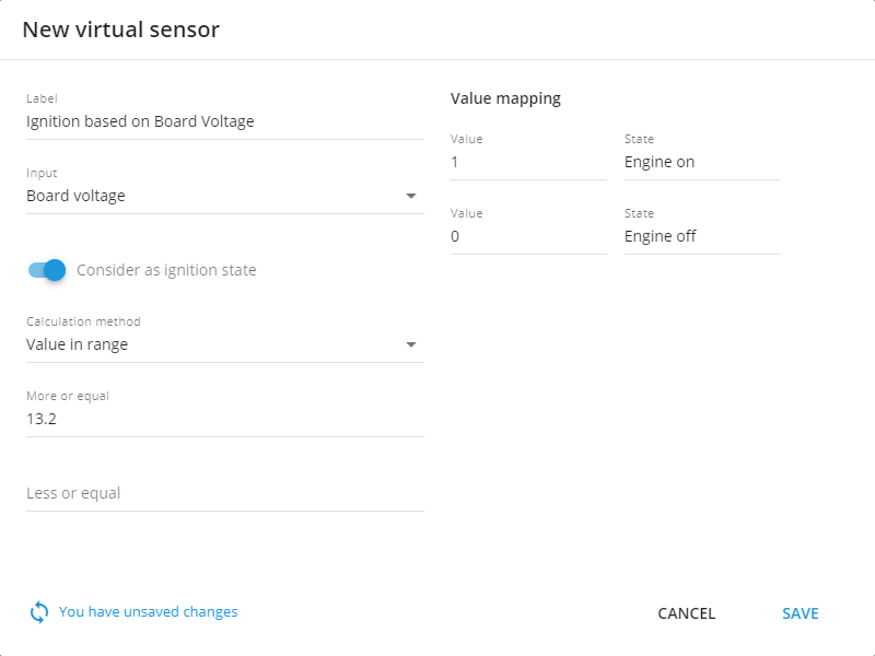
Example configuration for virtual ignition
Once you set your voltage threshold range, if the incoming on-board value is within that range, the platform will switch the ignition state to "on". Conversely, if it's outside of that range, it will be switched to "off". The virtual ignition created using this method will also be taken into account in reports and notifications based on its status; for example, you can use it to generate engine hours reports or alerts for excessive idling.
Additionally, this ignition will be used for trip and parking detection with ignition consideration.
Example with an analog sensor
This example is similar to the previous one, but instead of monitoring the vehicle's ignition, it monitors temperature.
Suppose you have an analog sensor that collects temperature data – let's say that it outputs 1020 for -10°C, and 1900 = 0°C. The data coming from the analog sensors is non-calibrated and so must also be specified in this form for the virtual sensor.
We can set our range – anything between 1020 and 1900 would be categorized as "cold" (1) and anything above 1900 would be considered "hot" (0).
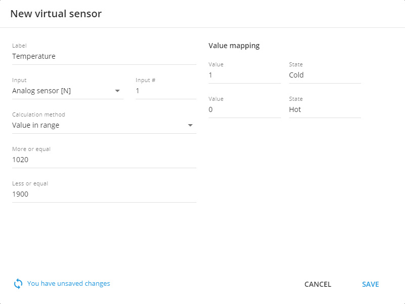
Example configuration for reading temperature from analog sensor
Source Value
With virtual sensors, you can assign your definition to any received values. This method works with predefined sets of values and strings, which makes it easy to work with static values without having to specify different ranges. In addition, it can work with any data you need. For example:
0/1,
true/false,
on/off,
open/close,
armed/disarmed,
state 1/state 2/state 3,
key 1/key 2/key 3, etc.
The mode works like this:
when value 1 comes in, that's your value A;
when value 2 comes in, that's your value B;
and when value 3 arrives, that's your C value and so on.
Let’s illustrate this type of functionality with a concrete examples.
Example with car CAN readings
Some CAN sensors may provide different numerical values to a platform. For instance, we have a truck with CAN: PTO state sensor which may output only the following values:
0 – Off
1 – Hold
2 – Remote hold
3 – Standby
4 – Remote Standby
5 – Set
6 – Decelerate
7 – Resume
8 – Accelerate
To configure such sensor:
Specify its name.
Choose the input.
Consider as ignition should be off.
Select "Source Value" as calculation method.
Fill out the table with your own values on the left side and its respective sensor values on the right. Add rows by clicking the "+" sign and delete them using the trash can button.
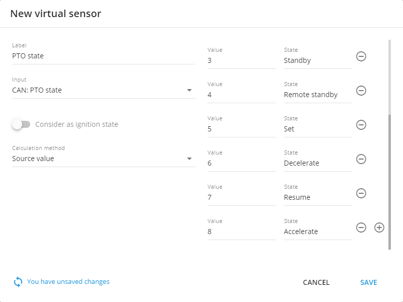
Configuration example for source value calculation method
Hardware key readings for drivers, equipment and trailers
Some devices may be able to read drivers and their iButtons, RFID keys or equipment connected via Bluetooth sensors to the device. The platform can detect the nearest equipment or driver to the device, and the Virtual Sensor is capable of displaying such names.
The simplest way of identification is through tags – each unit connected to a heavy equipment has its own sensor with a tag attached, which is recognized by the platform as a hardware key. When connected to the machine, this key will be sent to the platform and its associated name can be displayed in an understandable manner – similar to how values for PTO were named.
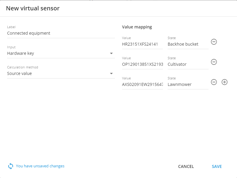
Configuration example for source value calculation method for hardware key or state field sensor reading
Bit index
Some devices may provide advanced data in their packets, sometimes merging several parameters into one value. The Virtual Sensors tool allows you to work with parts of telematics values, thereby decoding the data transmitted by the GPS hardware.
For example, let's say 011 value is transmitted – we must first read this information in little endian according the protocol:
1 - Shows the status of the driver's belt: 0 - fastened, 1 - unfastened. Bit 0
1 - Displays the status of the driver's door: 0 - closed, 1 - open. Bit 1
0 - Indicates the condition of the hood: 0 - closed, 1 - open. Bit 2
Each position in the parameter displays the value of different vehicle systems. In order to configure and display them, you need to create one sensor separately for each parameter.
For a sensor that shows the condition of the car hood in our example, you need to
Set the sensor’s name.
Choose the input according to the device’s documentation.
Select "Bit Index" as the calculation method
Choose bit 2 for this field.
Below is an example for a sensor that shows the condition of the car hood.
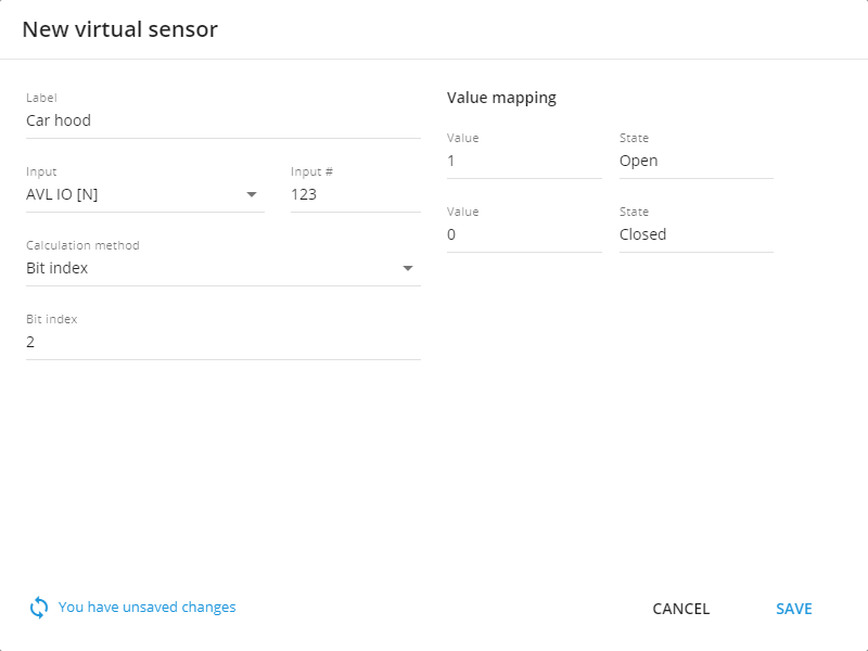
Configuration example for Bit index calculation sensor
Once a virtual sensor is configured and its associated device sensor has provided data, it can be viewed in the "Sensor Readings" widget on the device's Information tab. Your device sensors can talk in your language now.
