Flow management
IoT Logic provides a flexible canvas environment where you can build custom data flows to process, transform, and route device telemetry. Each flow consists of interconnected nodes that perform specific functions within your data processing pipeline, from receiving raw device data to forwarding enriched information to external systems.
Creating a new flow
IoT Logic starts with an empty workspace where you can design your data processing flow.
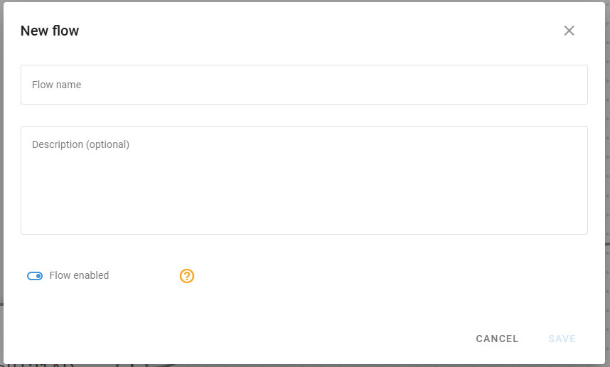
Create flow dialog
Follow these simple steps to create a flow:
Click the New flow button at the top of the screen to open the flow creation dialog.
Enter a Flow name and provide an optional Description to clearly show specific details about this flow's functionality or purpose.
Ensure the Flow enabled toggle is switched on (unless you're creating a flow that should initially remain inactive).
Click Save to create your flow and access the flow workspace.
The flow name and description help you identify each flow when you have multiple configurations. The enabled/disabled toggle provides a convenient way to temporarily stop data processing without deleting the entire flow configuration.
Disabled flows don't send any data! The readings from the devices involved in a disabled flow do not reach any destination, including the Navixy platform. This means that disabling a flow can interrupt your monitoring capabilities and data collection for the affected devices. Only disable flows when you deliberately want to stop data transmission completely.
After saving, your new flow appears in the workspace, and you can begin adding processing nodes from the left menu panel.
Configuring flow components
Each flow consists of interconnected nodes that define how data moves through your system. The basic components available in the Nodes pane include:
Data Source node
This node establishes the entry point for device data in your flow. It processes specific devices from your Navixy account that you can:
Filter by manufacturer and model
Specify the communication protocol
Select from one to an unlimited number of devices to send data into the flow
Easily select the whole device groups
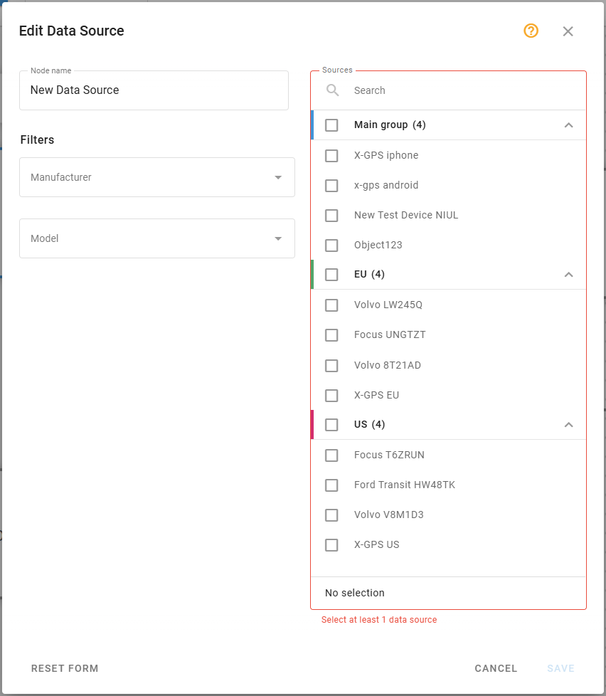
For detailed configuration options, see Data Source node.
Initiate Attribute node
This node enables data transformation through the Navixy Expression Language. It allows you to:
Create new calculated attributes based on device parameters
Perform unit conversions and mathematical operations
Apply time-based calculations
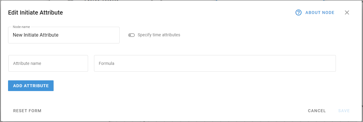
For detailed configuration options, syntax, and expression examples, see the Initiate Attribute node.
Logic node
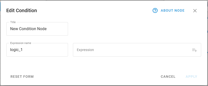
This node creates intelligent branching points that route data based on logical conditions. It allows you to:
Create conditional workflows with IF-THEN/ELSE logic
Route data through different processing paths based on real-time conditions
Generate boolean attributes that record validation results
Build complex decision trees with multiple conditions
For detailed configuration options, logical operators, and expression examples, see the Logic node.
Action node
This node enables automated responses to device data by performing specific operations when conditions are met. It allows you to:
Send commands back to devices based on data analysis
Trigger external system notifications or alerts
Execute automated workflows based on device status changes
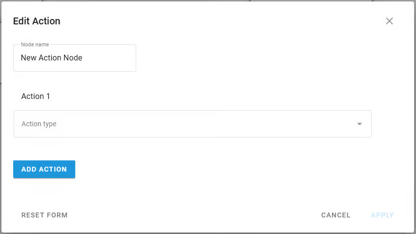
For detailed configuration options, see the Action node.
Output Endpoint node
This node defines where and how your processed data is transmitted. In its configuration, you can:
Specify destination connection details (IP/domain, port)
Select transport protocols and protocol versions
Set up security measures including SSL and authentication
Configure MQTT parameters like client ID, topics, and QoS levels
Create reusable endpoint profiles for consistent configurations
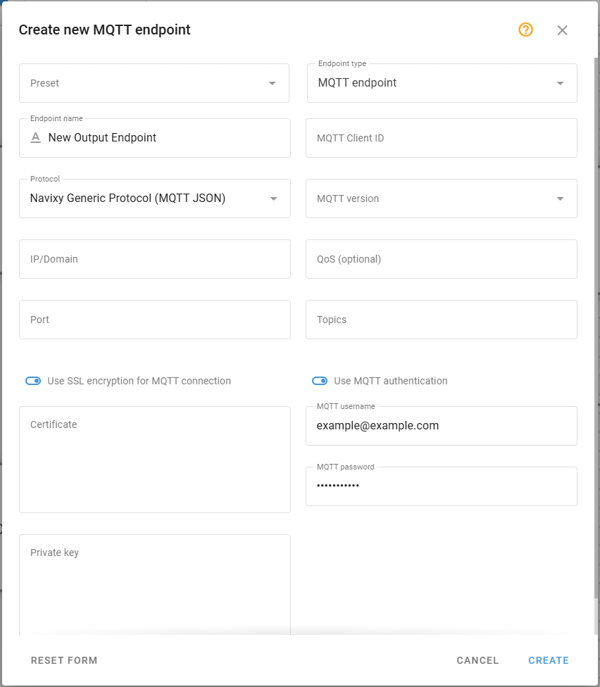
For complete details on data transmission options, see the Output Endpoint node.
Your flow should include a Default Output Endpoint to send data to the platform. Maintaining this connection ensures your device data remains available for visualization and management in the Navixy interface.
Building your flow
To assemble your data processing sequence:
Drag nodes from the left menu and drop them onto the workspace.
Click on each node to open its configuration panel and set up the required parameters.
Connect nodes by clicking on a node's output connector and dragging it to the input connector of the destination node.
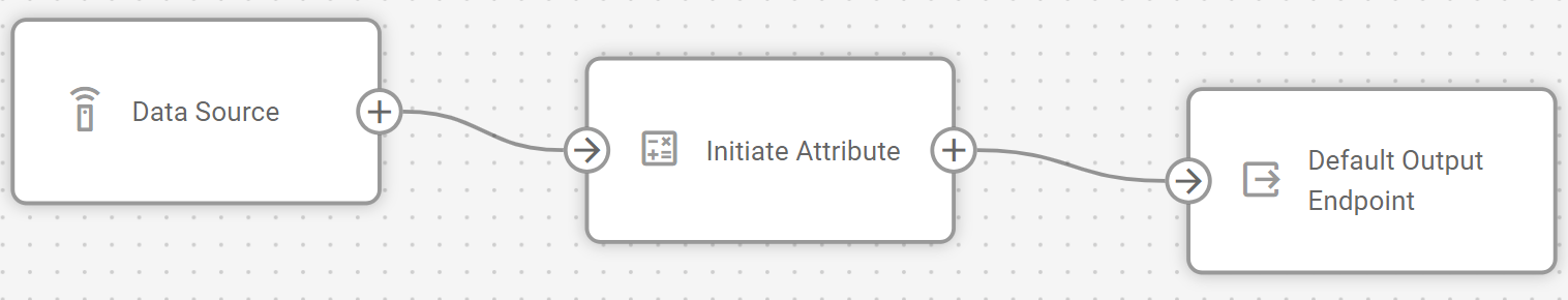
Created flow example
Your flow must begin with at least one Data Source node and end with one or more Output Endpoint nodes. Between these, you can add transformation nodes to manipulate the data according to your requirements.
Nodes can be connected in various configurations:
A single Data source node can feed multiple nodes for parallel processing
Multiple Data source nodes can connect to a single Output endpoint node to consolidate data streams
Initiate attribute nodes can be chained sequentially for multi-stage calculations
Editing existing flows
After creating a flow, you can modify its configuration as your requirements evolve.
Modifying flow details
To change the flow name, description, or enabled status:
Click
 next to the flow name
Update the desired fields
Save your changes
Removing elements
When you need to restructure your flow, you can remove nodes or connections:
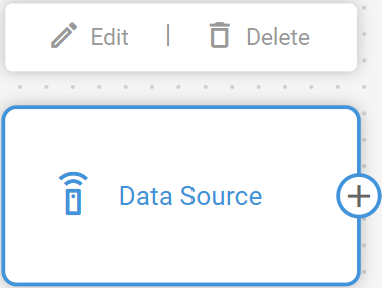
Deleting a node:
Hover your cursor over the node you want to remove
Click the delete icon that appears in the top right corner of the node
When you delete a node, all of its connections will also be removed.
Deleting a connection:
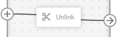
Click on the connection line you want to remove
Click Unlink or press the backspace key on your keyboard
Managing multiple flows
To switch between different flows:
Click the Data flow dropdown
Select the flow you want to view or edit, it opens on the workspace
Any unsaved changes in the current flow will be lost when switching, you will be asked to confirm the action.
Saving and activating flows
After configuring your flow:
Click the Save flow button to store your flow configuration
Ensure the flow is enabled for it to begin processing data
Once activated, your flow will:
Receive real-time data from the configured devices
Apply any defined transformations through Initiate attribute nodes
Forward the processed data to your specified endpoints in the Navixy Generic Protocol format
If you need to temporarily disable data processing, you can toggle the flow's enabled status without losing your configuration.
Example configurations
You can find detailed step-by-step descriptions of an example flow creation in Flow configuration example. The example also contains explanations on some common data enrichment options. Feel free to use this example as a template for your custom flows.