Intra-vehicle communication: CAN, FlexRay, and MOST
CAN, FlexRay, and MOST are all automotive communication protocols used to connect electronic control units (ECUs), transmission control units (TCUs), and body controlled modules (BCMs) in vehicles:
CAN
A message-based protocol that was originally designed to save copper by multiplexing electrical wiring in cars. CAN has a bandwidth of around 125 kpbs.FlexRay
A high-speed, fault-tolerant, and deterministic serial communication protocol that can transfer data at speeds of up to 10 Mbits per second over two twisted wires. FlexRay is often used in safety-critical applications, such as power train modules. FlexRay payloads, or data frames, can be up to 127 words (254 bytes) long, which is more than 30 times longer than CAN payloads.MOST
A bus standard for vehicle multimedia networks that allows for the transfer of high-quality audio, video, and data. MOST is available in three transmission speeds: MOST25, MOST50, and MOST150.
CAN (Controller Area Network) is currently the most widely used in-vehicle network. However, with contineous development in authonomous vehicles and related technology, there is a high demand for greater bandwith and connectivity. In this document, we briefly describe CAN and other vehicular connectivity options, including wireless CAN, MOST, FlexRay, and Automotive Ethernet.
CAN bus: some principles behind
In a broad sense, CAN-bus (Controller Area Network-bus) is actually a set of standards that enable different devices to communicate with each other. It is an asynchronous (time-shifted) serial bus system, developed in 1983 by Robert Bosch GmbH with a goal to interconnect electronic control units (ECU) in motor vehicles.
CAN was divided into various layers, following the ISO/OSI model to achieve flexibility and design transparency. For communication on practice, CAN bus uses two dedicated wires: CAN low and CAN high, by means of which CAN controller is connected to all the network components. CAN allows to substitute quite complex wiring with a two-wire bus. CAN uses a differential signal, that makes it more noise resistant, with two logic states: recessive and dominant. Nowadays CAN bus used pretty much all the way from coffee machines to fleet management and space applications. We briefly describe CAN bus working principles further.
The ISO-11898: 2003 CAN communications protocol explains how information is passed between devices on a network based on an Open Systems Interconnection (OSI) model that is presented as a set of layers on a figure below. The lowest two layers of the seven layer OSI/ISO model are the physical and data link layers. The physical layer defines communication between devices connected by the physical medium.
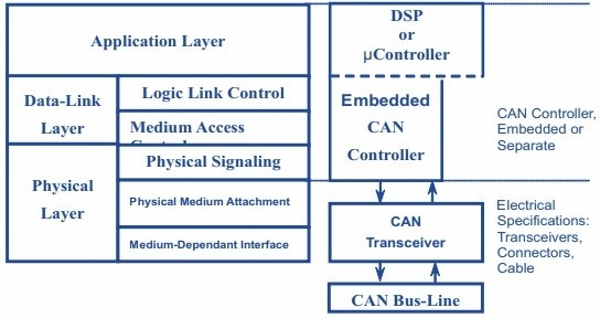
The Data-Link Layer among other things also takes care of organizing bits into frames and includes two protocols: classical CAN (first use backdated to 1988) and CAN FD (launched in 2012).
Application layer is essentially an end-user layer and provides access to network resources. There are two types of message/frames formats: standard and extended. They differ from each other just by the length of the identifier – a standard one is 11 bits, while extended one is 29 bits.
A standard message structure could be divided on 8 parts as shown on the figure below. Those parts are: Start of Frame (SOF - the start of frame transmission), CAN-ID (frame identifier, message priority identification), Remote Transmission Request (RTR, indicates whether a node requests data from another node or sends data), Control (informs the length of the data in bytes), Data (actual data values than needed to be scaled/converted), The Cyclic Redundancy Check (CRC, ensuring data integrity), ACK (acknowledge, indicates if the data being received correctly) and EOF (End of Frame) that labels the end of CAN message/frame.
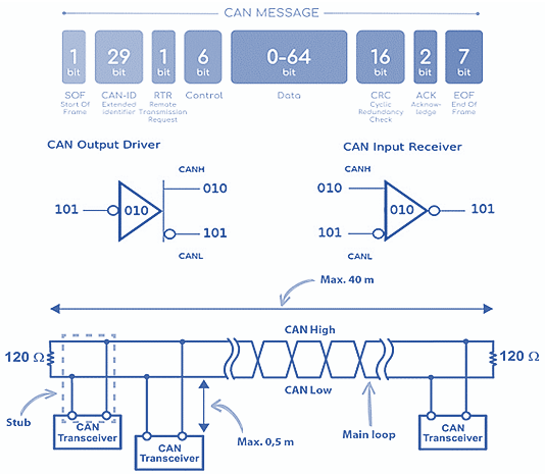
CAN bus utilize an inverted form of logic with two states: dominant and recessive. Figure above demonstrates a simplified input-output diagram of a CAN transceiver: bit stream going to/from a CAN controller and/or microcontroller. When the controller sends a stream of bits, these are complemented and placed on the CANH line.
The CANL line is always the complement of CANH. CAN must monitor both what is currently on the bus and what it is sending. For applications, both ends of the CAN bus must be terminated since any node on the bus may transmit data.
Each end of the link has a termination resistor equal to the characteristic impedance of the cable. Usually the recommended value for the termination resistors is 120 Ω (in a range 100 Ω - 130 Ω). There should be no more than two terminating resistors in the network, since additional terminations place extra load on the drivers.
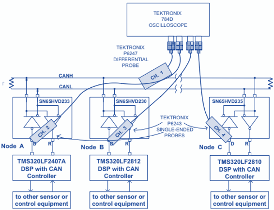
Figure below shows a CAN test bus. The nodes in figure could in principle be sending messages from smart sensing technology and a motor controller. A typical application could be for instance some temperature sensor.
Figure below shows a CAN test bus. The nodes in figure could in principle be sending messages from smart sensing technology and a motor controller. A typical application could be for instance some temperature sensor.
If another sensor node needs to send a message simultaneously, arbitration ensures that the message is sent. For instance, node A finishes sending its message as nodes B and C acknowledge a correct message being received. Nodes B and C on their turn begin arbitration and if node C wins the arbitration then it sends a message. Nodes A and B acknowledge message from node C, and node B then continues on with its message.
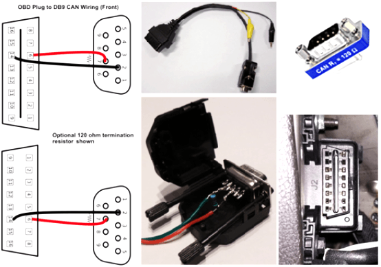
The opposite polarity of the driver input and output on the bus should be kept in mind. The CAN bus nowadays widely distributed in cars. It is present in pretty much all the vehicles being made. Cars in a modern world are essentially a global market product, so all vehicles tend to have a CAN bus. The CAN bus is accessed via the OBD port, that is shown on a figure below alongside with an example of a 120Ω termination resistor, soldered onto the DB9 connector with the CAN wiring, located in the DB9 shell housing.
For wiring the OBD port to a CAN DB9 device one needs a cable that can be either purchased or made. To get yourself a self-made one, a 9-pin D-sub socket (female) and an OBD plug (male) are required. The DB9 socket should match the plug for the CAN device.
An example of OBD plug to DB9 CAN wiring including optional termination resistor also shown on schematics below.
To build a sensor network, interface to a CAN bus, and view the CAN signals from vehicles there are a plenty of options. Various microcontrollers currently have the CAN protocol support and could be interfaced to CAN via a CAN transceiver chip.
Also solutions like Raspberry Pi, Texas Instruments Launchpad and Arduino are around and can interface to CAN by means of some add-ons. CAN communication network in modern vehicles could provide a huge data volume that can be utilized in fleet management to increase driver safety, reduce overall expenses, improve maintenance processes and support environmental responsibility.
Enabling CAN bus data provides fleet owners various opportunities to access various information including fuel consumption, odometer readings, revolutions per minute, throttle position, engine load/torque, engine temperature and fuel level.
CAN is currently the most widely used in-vehicle network. However, with continuous development in autonomous vehicles and related technology, there is a high demand for greater bandwith and connectivity. Further we briefly describe some other vehicular connectivity options, including wireless CAN, MOST, FlexRay and Automotive Ethernet.
Wireless CAN
CAN on a twisted pair of copper wires became an ISO standard in 1994. Growing demand on incresed connectivity gives a rise to development of alternative and complementary technologies. For instance, some options for wireless CAN transmission rely on protocol-based radio standards such as WLAN or Bluetooth.
In such scenario, CAN data in the transmitter must be converted to the wireless protocol and reset in the receiver. Transparent and real-time transmission in the sense of the CAN network is not possible in this way. The radio connection thus functions as a gateway between two CAN networks.
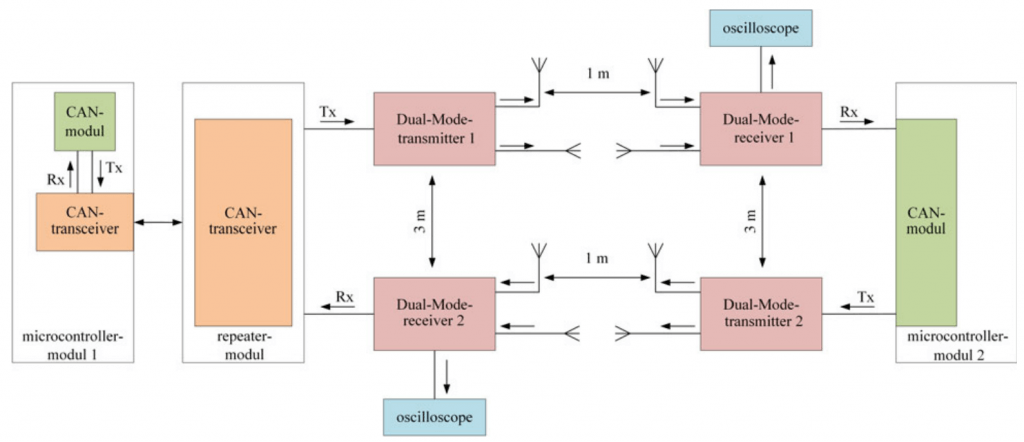
The wireless CAN that based on dual-mode radio enables CAN participants to be integrated wirelessly into a CAN network, increasing security and usability. However, such a system require special antennas that need space and a particular alignment that limiting omidirectional radiation.
MOST, FlexRay and Automotive Ethernet in brief
A promising alternative to CAN is automotive ethernet. Some estimations expect the automotive ethernet market to grow more than 21.6% over the forecast period 2019-2026.
Key ethernet benefits for vehicle connectivity are high bandwith and cost efficiency. Ethernet employ Carrier Sense Multiple Access with Collision Detection (CSMA/CD) strategy. Collision can be ignored through division in the in-vehicle networks. Some challenges of automotive ethernet are significant amount of RF noise, inability to provide latency down to the low microsecond range and lacking the way of synchronizing time between devices.
MOST (Media Oriented System Transport) is a serial communication system for transmitting control data, video and audio by means of fiber-optic http://cables.It provides a point to point sound and video information exchange with 24.8 Mbps speed rates. MOST created by MOST association and defines the protocol, software and hardware layers necessary to allow for the efficient and low-cost transport of control, real-time and packet data using a single medium / physical layer. A MOST network could be schematically presented in a form of ring that may include up to 64 MOST devices. Thanks to to its plug&play functionality, adding or removing MOST device should be pretty straightforward.
FlexRay on its turn is essentially an automotive network standard based on a flexible high data rate deterministic, fault-tolerant and high-speed bus system. It is utilized as a part of the star or line topology with copper or optical fiber. FlexRay featuring a dual-channel configurations offer enhanced fault-tolerance and/or increased bandwidth. The FlexRay communications network features making them favorable for next generation automotive industries.
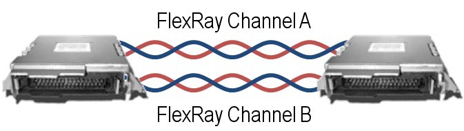
Most first-generation FlexRay networks normally employ a single channel to cut off wiring costs, but further applicatuions development and entailed security requirements will lead to increased two channels usage.Limiting factors for FlexRay widespread usage are price, lower operating voltage levels and edges assymetry, leading to challenges in extending the network length. Some key features of listed protocols as compared to CAN characteristics are presented on the table below.
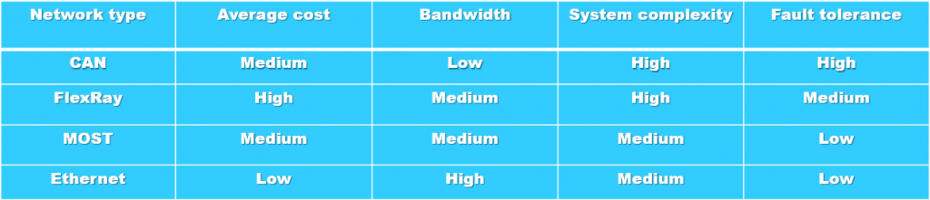
Direct comparison of listed connectivity protocols shows that there is a clear treadoff in bandwidth and fault tolerance versus average costs and system complexity. While CAN and MOST remain some sort of fundamental protocols, FlexRay and Ethernet are more promising solution to satisfy growing market and high load applications demands. In a modern vehicles, those protocols oftenly utilized as a complementary solutions.
Purpose of in-vehicle communication protocols
CAN bus is indeed a well known and established vehicle connectivity standard. It is fused for powertrain, chassis, backbone network and body systems. Ethernet on its turn is commonly used as a diagnostic protocol for engine, chassis, and body electronic connection control units used for network connections.
FlexRay currently forms the basis for active technology development worldwide, and its many applications include next-generation X-by-Wire systems and backbone systems. MOST is a bus standard for vehicle multimedia networks designed to enable transfer of high-quality audio, video, and data. It allows easy interconnection of vrious vehicle multimedia components.
All the above mentioned protocols and technologies technologies satisfy most of the requirements of diagnostics and multimedia communication for modern in-vehicle and vehicle to vehicle communication, and could be used for advanced autonomous driving systems, however the accurate integration of all those technologies while satisfying real-time constrints is still remain a challenging part.