Fuel level sensor calibration (tare)
Fuel sensor calibration
Accurate fuel level monitoring is crucial for efficient operation and maintenance of vehicles, machinery, and storage tanks. To ensure precise readings, fuel level sensor calibration, specifically taring, plays a critical role. In this article, we will delve into why taring is important, the workflow involved, and key aspects to remember during the process.
Why is calibration important?
Calibration refers to the process of setting the baseline or zero point for a fuel level sensor. It eliminates any errors caused by mechanical variations or electrical drift in the sensor, ensuring accurate fuel level readings. Here are some key reasons why taring is important:
Precision: taring allows for accurate measurement of fuel levels, enhancing operational efficiency and preventing potential issues arising from incorrect readings.
Cost Efficiency: Accurate fuel level measurements obtained through taring help optimize fuel usage, minimizing wastage, and reducing costs.
Maintenance Planning: Correct fuel level data enables proactive maintenance planning, preventing unexpected breakdowns, and ensuring optimal performance of machinery and vehicles.
Safety: Reliable fuel level readings are essential for safe operations, as they help prevent fuel leaks, overflows, and other hazardous situations.
Sensor calibration without additional accessories
Sensor calibration without additional accessories can be a challenging task as additional equipment and tools are often necessary for accurate calibration. However, there are some steps you can follow for a basic calibration process without additional accessories:
Identify Calibration Parameters: Understand the specific parameters that need calibration for your sensor. This could include factors such as sensitivity, accuracy, or zero offset.
Baseline Measurement: Take a baseline measurement of the sensor output in its current state. This will serve as a reference point for comparison during the calibration process.
Environmental Considerations: Ensure that the environment in which the sensor is located is stable and suitable for calibration. Factors such as temperature, humidity, or electromagnetic interference can affect sensor performance.
Controlled Input: If possible, provide a controlled input to the sensor to simulate a known condition. For example, if calibrating a temperature sensor, expose it to a stable temperature source such as a water bath or an oven with a known temperature.
Comparison: Compare the sensor output with the expected value based on the controlled input or reference source. Use appropriate measuring instruments or standards to determine the accuracy of the sensor readings.
Adjustment: If there are discrepancies between the sensor output and the expected values, make adjustments to the sensor settings if available. Some sensors may have adjustable calibration parameters that can be modified to improve accuracy.
Validation: Repeat the measurement and comparison process after making adjustments to ensure that the sensor output now aligns more closely with the expected values. If necessary, iterate the adjustment process until satisfactory results are achieved.
Documentation: Keep detailed records of the calibration process, including baseline measurements, adjustments made, and validation results. Proper documentation is crucial for traceability and future reference.
While the above steps provide a basic framework for sensor calibration without additional accessories, it's important to note that the accuracy and precision of the calibration may be limited without dedicated calibration equipment. In many cases, specialized tools and accessories are required to achieve accurate and reliable results.
Sensor calibration using a tube tank
The tube tank serves as a vital component in liquid level sensor calibration. Essentially, it is a plastic pipe measuring around 700 mm in length with an approximate inner diameter of 50 mm. One end of the pipe must be closed and hermetically sealed. Occasionally, manufacturers include the plastic pipe as a packaging material alongside the sensor itself. The tube tank process is a widely adopted method for calibrating liquid level sensors. This procedure entails using a tube-shaped tank adorned with precise volume markings to verify and fine-tune the accuracy of the sensor readings. In the following sections, we will explore a comprehensive overview of the sensor calibration process utilizing a tube tank:
Setup: Begin by acquiring or constructing a tube-shaped tank with clear volume markings along its length. The tank should be made of a material that is compatible with the liquid being used for calibration.
Preparation: Ensure the tank is cleaned thoroughly to remove any residue or impurities that could affect the accuracy of the calibration process.
Installation: Mount the liquid level sensor to be calibrated onto the tube tank. Follow the manufacturer's instructions for proper sensor installation, ensuring that it is securely attached and aligned.
Baseline Calibration: Before proceeding with calibration, establish a baseline calibration point. Fill the tube tank with the liquid up to a known reference mark, such as zero or a predetermined level. Record the sensor's output at this reference point.
Calibration Testing: Begin the calibration process by incrementally filling the tube tank, ideally using multiple known reference marks along the tank's length. For each reference mark, record the corresponding sensor output.
Data Analysis: Compare the recorded sensor outputs with the actual liquid levels indicated by the known reference marks. Identify any discrepancies or errors between the sensor readings and the expected values.
Adjustment: If there are deviations in the sensor readings, make appropriate adjustments to align the sensor's output with the actual liquid levels. This may involve modifying calibration settings or performing hardware adjustments on the sensor.
Validation: After making adjustments, repeat the calibration testing process to verify the accuracy of the sensor readings. Ensure that the sensor now provides accurate measurements across the range of liquid levels.
Documentation: Maintain detailed records of the calibration process, including baseline calibration, adjustments made, and validation results. Proper documentation is important for traceability and future reference.
Regular Maintenance: Sensor calibration is not a one-time task; it should be performed periodically to ensure ongoing accuracy. Factors such as sensor drift, environmental changes, or wear and tear may necessitate re-calibrating over time.
It's worth noting that the specific details of the tube tank calibration process may vary depending on the type and model of the liquid level sensor being calibrated. Always refer to the manufacturer's guidelines and documentation for precise instructions tailored to your sensor. Fuel tank calibration.
Tank Calibration is required to convert fuel readings in digital signals or volts into gallons or liters.
Full tank calibration
All calibration practices follow more or less the same routine:
Pour an accurately measured volume of fuel inside the tank. It’s called a pass. Each pass should be at least 1/10 to 1/20 (more recommended) of the total tank volume, e.g. 20 liters. This way the calibration table will have from 10 to 20 (more recommended) entries. There are many techniques that installation crews may apply to accurately measure fuel volume for one pass. For instance, transfer pumps with meters or portioning at the fueling station.
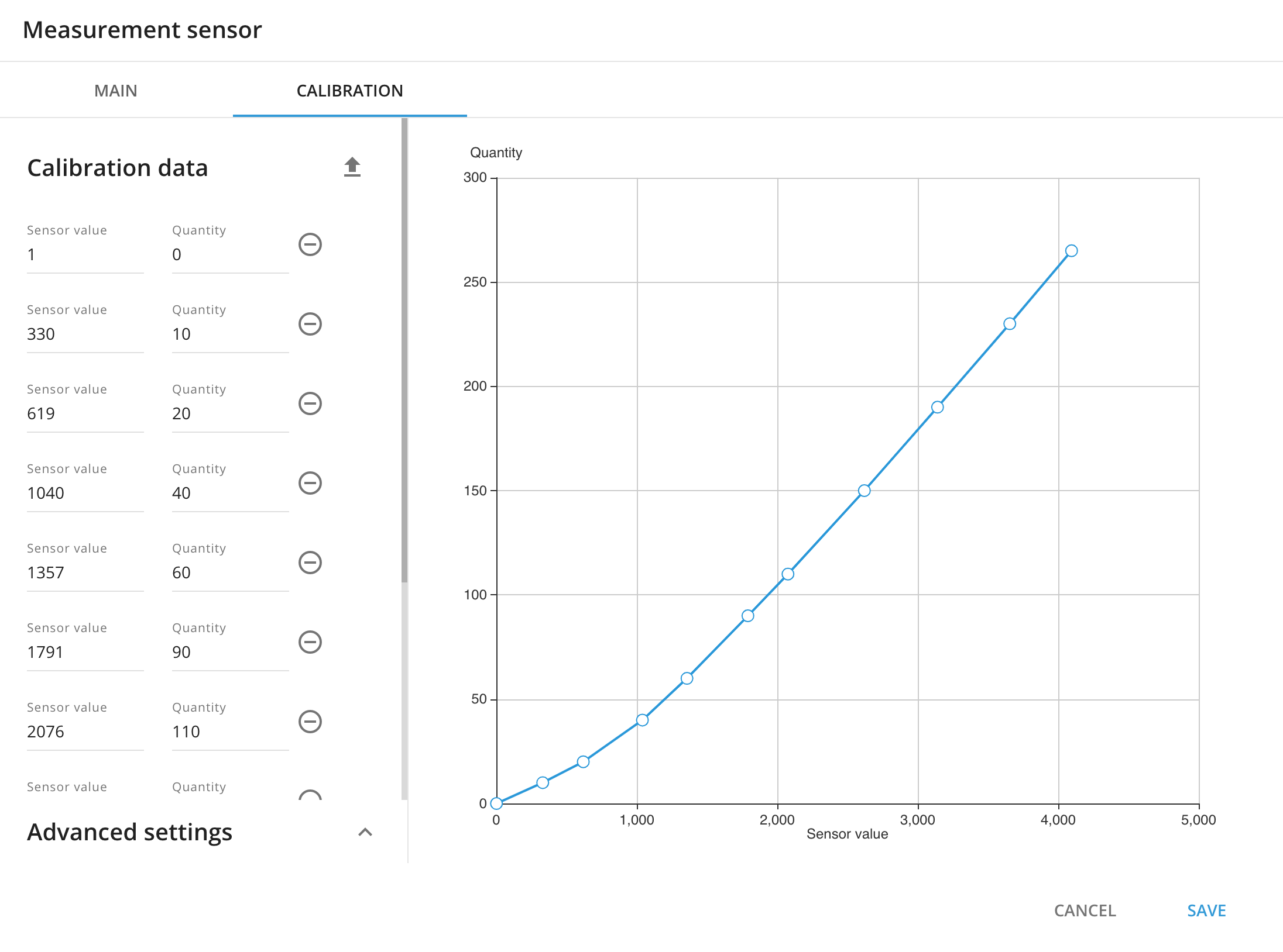
Check the value on the laptop. Make an entry to the calibration table as follows: sensor value - number of liters/gallons.
Make another pass and another entry to the table. Repeat until the tank is full.
If the tank has a complex shape, the pass volume should be divided by two when reaching the “crooked” spot.
Add the entries from the calibration table to the GPS tracking platform (Go to Devices and settings => Sensors and buttons => Add measurement sensor). Some sensors support the option of uploading tank calibration tables from a file (e.g. Fuel sensors by Omnicomm). Otherwise it should be added manually.
To delve into the art of creating and configuring sensors, alongside adding calibration data in Navixy, venture into the realm of the Sensors settings section. Discover a world of possibilities waiting to be explored!