Sensors setup and configuration
To carry out tasks involving sensor setup, configuration, and maintenance, it is recommended to access the Device and Settings menu.
With the "Sensors and buttons" portlet, you have the ability to easily incorporate new discrete and measurement sensors into the system. The collapsed panel conveniently displays the sensors currently connected to the selected device. Expand the panel to seamlessly add or edit a sensor as needed.
Fuel sensor creation
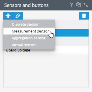
Fuel sensors are a type of measuring sensor that can be created on a GPS tracking platform. To create a fuel sensor, navigate to the Device Management section and click on the Sensors and Buttons panel. Next, click on the “+” icon and select "Measurement sensor" from the drop-down menu.
Fuel sensor settings
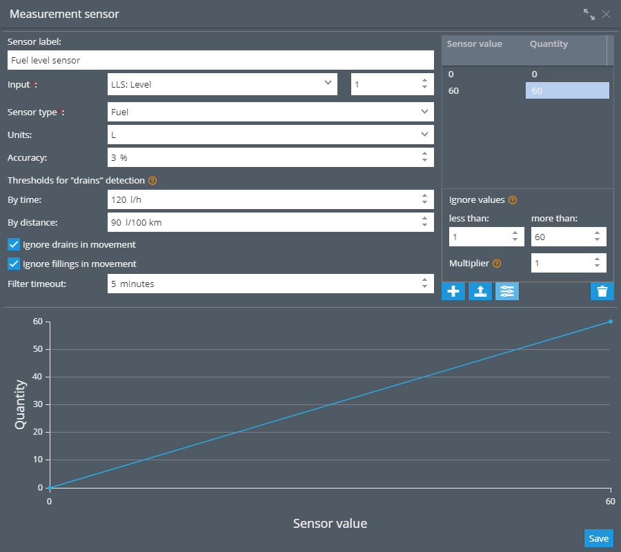
Upon selecting Fuel Level as the sensor type, you will be presented with additional settings. The comprehensive range of options available for the fuel sensor includes:
Sensor name - assign a clear and convenient name for the sensor. This name will be visible on widgets, reports, and rules to help you easily identify the sensor.
Input - select the input from which the device transmits fuel data.
Units – select a unit of measure.
Accuracy - this refers to the specified percentage used to calculate the percent error in tank volume. This error value will be used to compute the amount for refills and drains.
Thresholds for drain detection - are used to determine drains in fuel reports. This parameter can be represented as the rate of change in the fuel level. Both thresholds are always checked, and if the fuel level changes faster than at least one of the set thresholds for more than accuracy level, the report will mark the fuel drain. We have described it in detail in analyzing fuel volume report.
By time - maximum allowable flow rate is measured in units per hour and can be set in the sensor settings. When calculating the speed change over time, the platform compares the fuel level change between points. If it is not set, the default value is 120 units per hour. It doesn’t mean the fuel must change more than 120 per hour. It means the fuel level should change faster than 120 per hour (equal to 20 L per 10 minutes or 2 L per minute) to determine the drain in a report. This value should be set a few percentage points higher than the likely consumption rate during heavy loads or when the vehicle is ascending uphill.
By mileage - the maximum allowable fuel level change speed is measured in units per 100 km. It doesn’t mean the fuel must change more than set per 100 km. For example, we set 100 L per 100 km. It means the fuel level should change faster than 100 L per 100 km (equal to 10 L per 10 km or 1 L per km) to determine the drain in a report. This value must be manually entered and should not be based solely on the manufacturer's specified fuel consumption rate. We recommend conducting tests and verifying the actual fuel consumption rate recorded in the reports, then set the necessary values accordingly for maximum accuracy.
Ignore in movement - the platform will automatically exclude any drains and refills that occur during movement from rules and reports. Movement is determined by the Parking Detection setting.
Drains – drains in movement will be excluded.
Refills – refills in movement will be filtered.
Filter timeout - This setting appears when the Ignore feature is enabled. It determines the timeout period in minutes that will be used to shorten the driving intervals for fuel filtering. This option can be helpful if the fuel level stabilizes only after some time has passed since refueling, and the vehicle has already started moving. This is more commonly seen in vehicles with large fuel tanks. The default setting for this feature is 5 minutes.
Calibration table - this parameter is used to convert the sensor readings into desired units such as liters. Some sensor manufacturers may provide the conversion values for the table. But we strongly recommend to do calibration in order to achieve accurate readings.
Tank volume - is the maximum volume of the tank, which is specified in units in the calibration table. If calibration values are not specified, the default value of 100 is assumed, which indicates that the data is being transmitted in percentage.
Even if your sensor already sends data to the platform in liters, it is better to specify the calibration as 0 = 0 liters and maximum fuel tank capacity = X liters.
If it is a sensor that transmits fuel level information in percentages, specify calibration 0 = 0 liters and 100 = maximum fuel tank capacity in liters.
Advanced settings - are below the calibration table.
Ignore values - values should be specified the same way they come to the platform from the device.
Less - the filter can be used to ignore any readings that fall below a certain threshold, X. This is helpful in situations where a sensor's readings may fall below a certain value. For example, a loose wire or a sensor that sends a reading of 0 when the ignition is switched off.
More - the filter can be used to ignore any readings that exceed a certain threshold, X. This is valuable when dealing with sensors whose readings may occasionally increase dramatically. For example, if an error is detected or if there is a higher voltage than expected.
Multiplier - multiply the resulting values by a certain coefficient. If you want to divide values, use decimals.
Adding calibration data
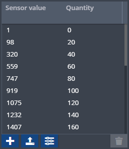
Once all parameters are configured, it becomes imperative to incorporate calibration data into the table. Begin by obtaining a comprehensive lineup that correlates the raw values of the measurement sensor (e.g. volts) with the corresponding actual measurements (e.g. liters). To append additional rows to the table, simply click the designated button.

In the created line, fill in the "Sensor value" field with the obtained value, and the "Quantity" field with the corresponding measured quantity.

To delete a row, click .

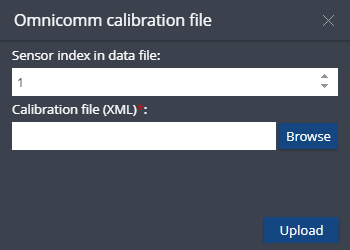
To upload the calibration table file, click . Calibration files can be generated by Omnicomm LLS Monitor utility. Only XML file format is supported.
For more precise setting, click "Advanced settings" button . These settings are Ignore values and Multiplier.

Ignore values – this setting allows you to adjust a "valid" range of raw measurement values. Any values above and below the range will be omitted. For example, this can be used for skipping zero values of fuel sensor when the vehicle ignition is off.
Multiplier – used to correct raw data values from the sensor by multiplying them by some number.
Filtering order
Please keep in mind that the "less than" and "more than" restrictions are
applied before the "Multiplier". The entire order of filtering:
Ignore values (less than & more than)
Multiplier
Calibration table
E.g.: Incoming raw value - 1000, boundaries are 3000 and 100, multiplier equals 0.2.
In this case, the value passes through the min/max filter, is multiplied by 0.2 and becomes 200. And this is where calibration table applies. Calibration table takes 200 as the "Sensor value" (source value) and converts it into the target "Quantity" value to be displayed in the user interface facilities. If an incoming data packet contains the sensor data with a value more than 3000, the value will not pass the boundaries, it is discarded, therefore, no multiplication and no calibration apply.
The numbers here are for example and you may have other settings but the principle remains.
Checking graph
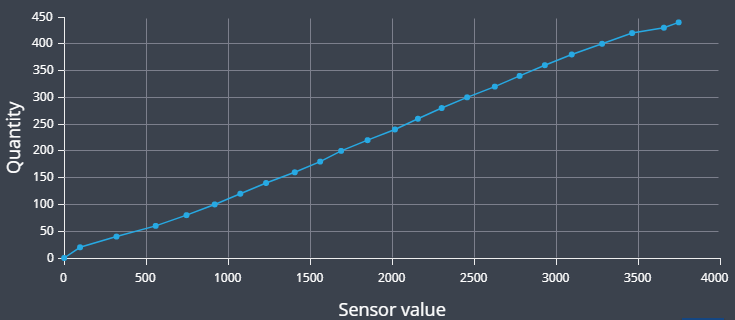
As you enter data into the table, the graph will be plotted.
If the table is filled in correctly, the graph will increase monotonically:
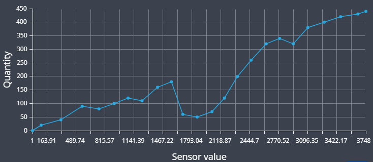
If the graph does not increase monotonically (e.g at first increases and then decreases, or looks wavy), then the calibration table incorrect:
To confirm your changes, click Save.