Fuel level sensor installation
We strongly recommend engaging the services of professionals for the installation of your equipment.
To get the sensor up and running it takes:
2 technicians
Installation tools
Bi-metal hole saw
Corner drill
Metal drills (look for HSS-TiN drills)
Flat head and Phillips head screwdriver
Pliers
Hack saw or tube cutter
Riveter (to fix the sensor to the thick-walled tank)
Calibration set
Calibration tube
Portable gas station - required during tank calibration for precise measurement of fuel level
Tanks for temporary fuel storage (often inflatable/ collapsible fuel tanks)
Consumables – U-bolts, corrugated tubes, etc.
Laptop – to calibrate the sensor and the fuel tank
USB Connector kit (to connect the sensor and the laptop). Usually sensor manufacturers make their own USB adapters (e.g. UNU-USB by Omnicomm) to fit the sensors.
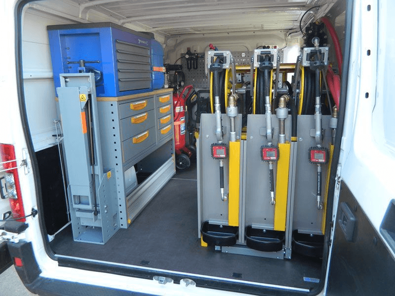
Quite often technical crews operate an all-in-one mobile calibration station, which has everything from tanks for draining the fuel to a refilling station on one vehicle.
And last but not least, installation of fuel sensors requires knowledge, skill and expertise to deal with all kinds of tanks and situations.
Now let’s have a closer look at installation processes for each fuel sensor type.
Installation of ultrasonic fuel sensors
Tank external surface should be polished at the bottom area, where the sensor will go. Then the sensor must be glued to the tank and fixed with a metal band, wrapped around the tank. Afterwards the sensor is connected to the power supply and calibrated.
Now let’s take it step by step:
Before you start with ultrasonic fuel sensor installation, the first thing to do will be to find the center of the bottom of the tank.
The bottom of the tank shall be ground to the metal at the spot the sensor will be attached to.
Apply glue on the sensor - make sure the glue is included in the supply package!
Press the glued sensor hard to the tank and fasten it with a metal band, wrapped around the tank.
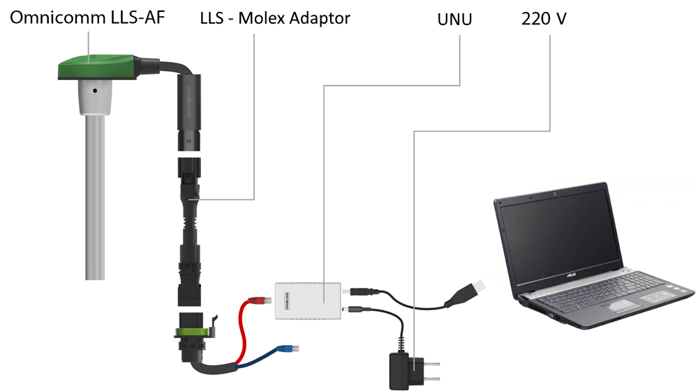
Connect the sensor to the dashboard and to the laptop using a special adapter. Download the software for sensor calibration.
Calibrate the tank.
Disconnect the sensor from the laptop and connect it to the tracker.
For rectangular tanks, the center of the bottom can be found by drawing diagonals and where they meet in the middle will be the center.
The installation usually takes approximately 4 hours.
Installation of capacitive fuel sensors
Installation of a capacitive fuel sensor begins with removing the tank and any residual fuel within it. For the next step cut a hole to fit the sensor and screw it to the tank. Connect the sensor to the power supply, calibrate the sensor, and the tank.
Now let’s review each step more in-depth.
Before the installation, drain fuel from the tank and remove any fuel vapors. This step is very important! Don’t skip it, otherwise sparks from drilling the opening will cause an explosion, especially in petroleum vehicles. Fill the tank with water and steam it.
Define the geometric center of the tank.
Drill an opening at the geometric center. Warning: take precautions to prevent metal chips from getting inside the tank.
Measure the depth of the tank. The tubes shouldn’t touch the bottom of the tank for fuel to easily get inside the sensor. A hacksaw or a tube cutter will help you adjust the length of the sensor.
Connect the sensor to the dashboard and the laptop using a special adapter. Download the software for sensor calibration.
Calibrate the sensor. The fuel sensor needs to adapt to its new length. Put the sensor upside down (with measuring tubes facing up) and fill it with fuel. Keep the fuel for 1-2 minutes and drain it.
Install the sensor, so the measuring tubes will be inside the tank, while the electronics + PCB and cables - outside the tank.
Fasten the sensor using self-tapping screws
Calibrate the tank
Disconnect the sensor from the laptop and connect it to the tracker.
The installation will take approximately 4 hours. For more information watch OMNICOMM installation training video (10 min).
Please consider the following important points. When the working portion of the sensor is less than 500 mm, it is crucial to set the range to 1024, as failing to do so could result in a notable margin of error in the data. Taking this into account will ensure accurate and reliable measurements.
Connection to the CAN bus
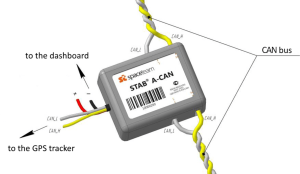
CAN bus is a twisted pair (two wires twisted around each other). To find the CAN bus in your vehicle, refer to the wiring diagrams, otherwise it will be difficult to find it within the vehicle.
Once it is located, you can connect to it via a CAN Crocodile contactless reader (recommended) or connect to it directly.
Find out the vehicle brand, model and year of manufacture before connecting to its CAN bus.
Check the vehicle manuals to make sure that the CAN bus monitors fuel level data. Unless it does, the other steps will make no sense.
Go to the tracker manufacturer’s website to select a CAN module brand that fits.
Choose the CAN module type/model based on your vehicle or heavy equipment type.
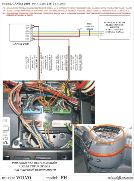
CODEFor instance, Teltonika requires different CAN module for cars (LV-CAN 200) and for trucks (ALLCAN 300).Ask the CAN module vendor to supply a connection diagram for your vehicle brand, model and year of manufacture. Usually it takes not more than 30 min to find the right diagram.
Connect the CAN module the way it is shown in the diagram.
Use a a mini-USB to USB cable to connect the CAN module to the dashboard and the laptop with pre-downloaded setup software.
Insert the number given in the diagram to set up the CAN module.
Disconnect the CAN module from the laptop and connect it to the GPS tracker.
Perform a lite tank calibration.
The installation will take approximately 30 minutes (considering the diagram is available).
Fuel sensor outputs
As of 2018, the most common outputs to connect to GPS trackers were:
For factory installed trackers:
analogue output
CAN interface
For additionally installed trackers:
analogue output
frequency output
digital output:
RS-232
RS-485
CAN-2 interface
Bluetooth radio interface
Other radio interface
Analogue signal
Equipment: Fuel sensor with analogue output, GPS tracker with analogue input
Specifications: in this case fuel level data is transmitted to the GPS tracker as voltage (potential difference between the sensor output and the ground, DC). The higher the fuel level, the higher the potential difference is.
For instance, 1V stands for an empty tank, 10V stands for a full tank. A tank calibration is required to convert the volts into litres or gallons.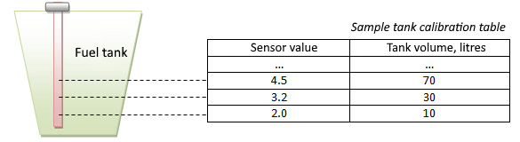
GPS trackers will transmit the values to the GPS tracking system in volts (e.g. 6.35 V).
Advantages: you can use a cheap and simple GPS tracker with basic outputs only.
Disadvantages: readings accuracy is affected by voltage fluctuations, wiring condition and age, as well as other factors contributing to error.
Application: you can recommend analogue fuel sensors if your clients’ GPS trackers have no digital inputs (analogue inputs only) or if the client is looking for a cheapest solution.
Frequency signal
Equipment: fuel sensor with frequency output, GPS tracker with frequency input (e.g. BCE Blue).
Specifications: in this case fuel level data is transmitted to the GPS tracker as an impulse frequency (for instance, in the range from 30 Hz to 2000 Hz). The higher the fuel level, the higher the frequency is.
For instance, 30 Hz stands for an empty tank, 2000 Hz stands for a full tank. A tank calibration is required to convert frequency into liters or gallons.
Data modulation techniques work just like the well-known FM radio. In this case an analog sensor acts as an AM-radio, where the signal is amplitude modulated (More on amplitude modulation here). Frequency modulation for fuel level sensors emerged after analogue modulation but before digital signals. It is more resistant to noise than the analogue signal, but not as noise-free as digital signals, and is basically not used anymore.
Advantages: less error than in analogue signals. Frequency signals are quite often used as auxiliary ones for analogue sensors. In this case they are called frequency-analog sensors.
Disadvantages: cost-effective GPS trackers rarely have frequency signal options
Advantages: fuel sensors with frequency signals are much less widespread than analogue or digital solutions. However, you can recommend these sensors to your clients if the other options are not available.
Digital signals
Equipment: Fuel sensor with digital output RS-232 or RS-485, GPS tracker with RS-232 or RS-485 digital inputs.
Specifications: fuel level data is transmitted as digital signals (conventional numbers without units of measurement) over the copper wires. A GPS tracking platform will get these readings as positive integers, usually the 2byte characters from 0 to 65535. A tank calibration is required to convert the numbers into liters or gallons.
Advantages: ultimate noise immunity during signal transmission (compared to analogue signals). It also provides more accurate readings than analogue fuel sensors. Ability to connect more than one sensor on one tracker (through RS-485 interface, RS-232 allows to connect only one sensor). Check the GPS tracker manufacturer’s website to see the number of fuel sensors to be connected via RS-485.
Disadvantages: GPS trackers with digital signals are usually more pricey than similar trackers without digital inputs.
Application: If a client wants to monitor fuel level for their vehicles, then a digital interface should be a go-to solution. Make sure you consider whether the GPS tracker has RS-232 or RS-485 input.
CAN bus
Equipment: CAN module for CAN data reading, CAN module-compatible GPS tracker or OBD2 GPS tracker supporting OBD data reading.
Specifications: the GPS tracker will use fuel level data from the factory-installed fuel sensor. These readings will be transmitted as a % of the total tank volume. A lite tank calibration is required to convert % into gallons or liters.
Advantages: fast non invasive installation or DIY installation in case of OBD2 tracker. No extra money spent on sensor setup.
Disadvantages: less accurate than a capacitive sensor. Some vehicles (usually the older ones) don’t transmit fuel level data via a CAN bus.
Application: feel free to recommend this option if it is impossible to install a capacitive fuel sensor on the vehicle. Don’t forget to check if the vehicle’s CAN bus does transmit this data.
Bluetooth
Equipment: Bluetooth fuel sensor, GPS tracker with Bluetooth connectivity, compatible with the fuel sensor. For instance ESCORT TD-BLE
Specifications: fuel level data is transmitted as digital signals over the wireless bluetooth channel. A tank calibration is required to convert the characters into gallons or liters.
Advantages: wireless sensors require easy and cheaper installation. The latest models have no wires at all, not even for the power supply. They are already equipped with a battery for the whole life span of the device thanks to Bluetooth Low Energy (BLE). Some say that wireless fuel sensors are the future.
Disadvantages: every wireless fuel sensor manufacturer has their own data transmission protocol (a unified or simply a market-leader protocol is not yet acquired). Thus every GPS tracker manufacturer should consider compatibility with fuel sensors of every make. Besides, as any emerging technology, the wireless options cost more than their wired alternatives.
Application: if the client’s GPS tracker has a Bluetooth connection, then a wireless fuel sensor can be the right choice.
Fuel sensor design: Unorthodox solutions
Many fuel sensor manufacturers provide their devices with additional features. Some of them can be quite cutting-edge and useful.
Remote power monitoring
If a fuel sensor suddenly goes offline, the first thing to do will be to check if it is connected to any power supply. Some sensors, e.g. manufactured by Siensor, allow for remote power monitoring. These fuel sensors have one extra wire connected to an analogue or discrete input of the tracker. Add a new discrete or measuring sensor on the platform and stay aware.
Fuel temperature monitoring
Do your clients really need fuel temperature monitoring on a daily basis? Hard to say. Yet it’s good to know it’s there by default. That’s why some sensors manufacturers (TechnoKom, for instance) provide this option.
Universal outputs
Modern fuel sensors can be powered with both analogue and digital outputs. It’s a great solution for the customers who already have GPS trackers on board. Sometimes clients don’t know what inputs are already taken, so it’s good to have an alternative. Universal fuel sensors are provided by a few manufacturers, for example, Escort.
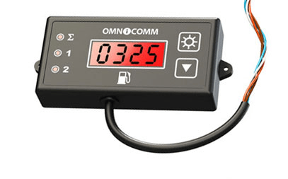
Fuel level indicator
Fuel level indicator is installed directly in the driver’s cabin to show the exact fuel sensor reading. It works both ways: managers will always see the fuel level and the drivers will always know the fuel is being constantly monitored (any fuel thieves will be caught red-handed). Below you can find a fuel indicator by Omnicomm.
Bent tube design
Should the fuel tank have a complex shape, the sensor tubes can be bent with the help of a bending machine (one bend only, not exceeding 70 degrees). The option is provided by a few manufacturers.
CANlike bus / S6 Interface
Technoton, a world-famous Belarus-based manufacturer, promotes the idea of a single interface for factory-installed and additional sensors (including fuel sensors). Technoton offers CAN 2.0 for this purpose. Their fuel and other sensors are connected to the vehicle CAN bus, just like factory-installed devices, to transmit the fuel level data.
This approach yields a few benefits. Mainly it removes any limitations on the number of devices to be connected to one tracker. However, fuel sensors operating on CAN interface will cost more compared to similar solutions with other outputs. That’s why this technology hasn’t become widespread.
Explosion-proof version
Some Safety rules and regulations require fuel sensors to be explosion-proof (e.g. if the sensor is installed inside fuel tankers). These sensors have a specific design to provide enhanced explosion and fire safety confirmed with a test certificate.
GPS tracker meets fuel sensor
In 2016 some fuel manufacturers came up with the idea to install a GPS tracking module on a fuel sensor directly (like in DUT-E GSM by Technoton). So if your clients only need to track and trace the location and to monitor the fuel level, then they will need to install just one single device, which is a big plus. However it limits (but doesn’t eliminate completely) any other devices to be connected to such a tracker+sensor set. Besides, any compound solution is always a compromise, which will take its toll on the commonly used GPS tracking features.