Fuel flow meter installation
We strongly recommend engaging the services of professional installers for the installation of your equipment.
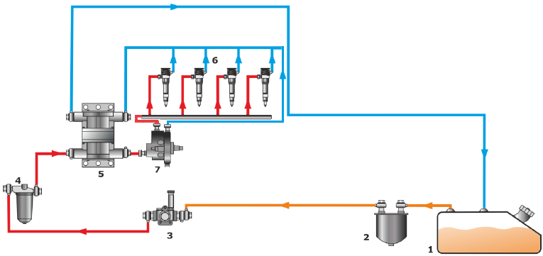
A flow meter is a vital component installed in vehicles or special equipment's fuel system. Let's revisit the typical scheme of the fuel system once more:
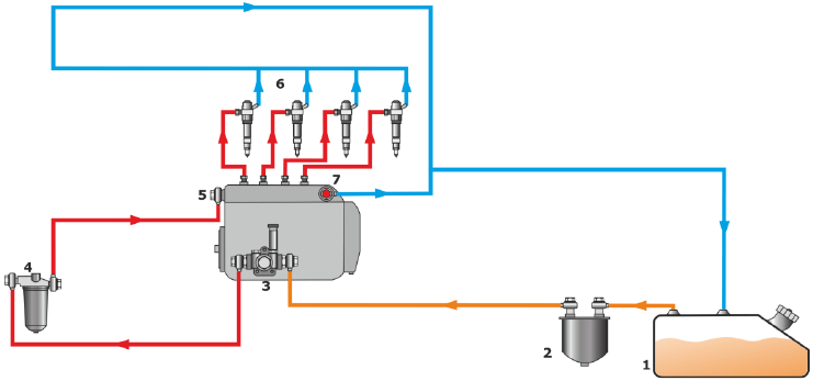
Typical diagram of a diesel engine fuel system
Fuel tank
Rough filter
Low-pressure fuel pump
Fine filter
High-pressure fuel pump
Injectors
Bypass valve
A flow meter can be installed:
Between the rough filter and the low-pressure fuel pump (within the supply fuel line). This scheme is called “On suction side”.
Between the fine filter and the high-pressure fuel pump (within the supply fuel line). This scheme is called “On pressure side”.
Depending on the type of flow meter selected (single-chamber or differential), it may be necessary to make certain changes to the fuel system.
To install a flow meter you will need:
An installer. On complex fuel lines, the help of several installers may be needed
A mounting kit
A bracket
Automobile hand tool kit (cap key, drive socket, and screwdriver sets)
A welding machine (preferably of an inverter type)
Pyrometer
Pressure gauge
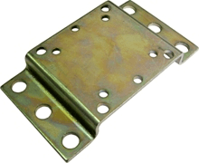
Mounting bracket for fuel meter installation
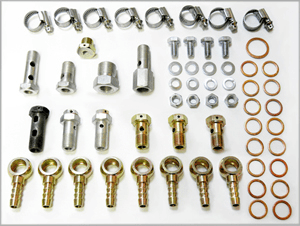
Fuel meter mounting kit
Flow meter installation routine
Irrespective of the chosen flow meter and connection scheme, the installation process requires the following actions to be undertaken:
Ensure smooth and stable operation of the engine by following these steps. Start the engine and carefully observe its performance for 5-10 minutes at idle and then 5-10 minutes while under load. It is crucial that the engine runs consistently, does not stall, and shows no signs of power loss. Remember, after installing a flow meter, there may be a decrease in fuel supply to the engine, which could potentially exacerbate existing problems.
Ensure thorough inspection of all fuel lines in the vehicle to identify any damages or fuel leaks. Installing a flow meter may cause a reduced amount of fuel to reach the engine, potentially resulting in insufficient fuel supply.
Utilize a pressure gauge to measure the pressure in the fuel line. This helpful tool provides accurate readings of the fuel line's pressure under different engine operating conditions, such as idle or maximum speed.
Avoid high-temperature areas with vibrations. Choose an installation scheme taking into account a flow meter’s possible location, it can be either “On suction” or “On Pressure”.
Screw a mounting bracket to the vehicle frame area. A bracket is a special metal plate to which a flow meter can be bolted.
Break the fuel line at the connection point with the flow meter. The existing fuel lines are removed and the new ones are installed in their place (usually they are reinforced hoses). Later, several kit items are installed at the ends of the new pipes in order to:
connect to the flow meter inlet
connect to the flow meter outlet
receive fuel from the return fuel line (depending on the installation scheme)
The new fuel lines need to have some spare length in order to compensate length changes due to the temperature.
To prevent air in the return pipe, it is recommended to install a fuel deaeration system. By utilizing a deaerator, air bubbles can be effectively eliminated from the fuel line, ensuring accurate measurements and uninterrupted flow through the measuring chamber.
Drilling into the vehicle frame is strictly prohibited when fitting the mounting plate for the flow meter. In case the use of bolts is not feasible for attaching the mounting plate, spot welding is an acceptable alternative.
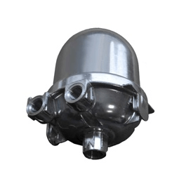
Technoton DFM DA 250 deaerator
For proper operation of the modified fuel system, install a bypass valve at the high-pressure fuel pump output, which will support the necessary pressure and help to prevent:
Fuel flowing in the opposite direction
Fuel system’s hydraulic shocks
Mount a fuel return line depending on the selected flow meter and the installation scheme. The mounting process is described above.
With the help of a low-pressure fuel pump, remove the air from the fuel supply line. To do this:
Loosen the bracket at the fuel injector inlet
Manually pump the fuel with the help of a low-pressure fuel pump
Make sure that there is no air coming from the the injector inlet
Fasten the bracket
To assess the fuel line pressure at various operating modes of the engine, such as idle or maximum speed, utilize a manometer. This data can then be compared to the previous readings obtained prior to installation. It is essential to ensure that any deviation observed does not exceed 5%.
Connect the flow meter to the onboard power supply and a laptop through an adapter (the same as with FLS). Then, configure the sensor with the help of a special application on your laptop.
Universal Adapter
Disconnect the flow meter from the computer, then tie an interface cable with a cable route. Connect the opposite side of the cable route to the GPS tracking device.
The installation of a flow meter can vary in time depending on the fuel system, ranging from 4 hours to 3 days. It's worth noting that ships, which often necessitate non-standard connectors for fuel pipes, require the longest installation time. Prior to commencing the mounting process, it is crucial to consider the availability of such connectors near the installation site, as obtaining them may prove challenging.
Video on flow meter installation on a tractor (20 minutes).
Single-chamber flow meter installation — On suction side
Installation of a single-chamber flow meter according to the “On suction side” scheme is as follows:
Single-chamber flow
Installation of a single-chamber flow meter as per “On suction side” scheme:
Fuel tank
Rough filter
Low-pressure fuel pump
Fine filter
High-pressure fuel pump
Injectors
Additional fine filter
Non-return valve (*recommended)
Bypass valve
Single-chamber flow meter
The following changes will be made to the standard fuel system:
The fuel line scheme for the return system has been modified. As part of the modification, the line that originates from the bypass valve of the high-pressure pump needs to be rerouted to the input of the low-pressure fuel pump. This adjustment eliminates the requirement to account for fuel from the return line. It is important to note that the return line from the injectors remains unchanged. When the injectors function properly, their return flow is minimal, constituting less than 0.1% of the overall fuel consumption. Therefore, this amount can be considered insignificant.
An extra fine filter is placed between the rough filter and the flow meter. Its purpose is not only to prevent the measuring chamber from getting clogged but also to serve as a deaerator when there is minimal air present in the fuel. This ensures optimal functionality and efficiency.
Advantages:
minimal interference into the fuel system;
easy installation;
applicable for most engines.
Disadvantages:
requires installation of an additional fine filter and causes extra costs;
additional load on the low pressure fuel pump;
fuel in the tank is not heated by a return flow line (fuel heater is sometimes required).
Single-chamber flow meter installation — On pressure side
Installation of a single-chamber flow meter according to this scheme is as follows:
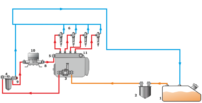
“On pressure side” scheme
Installation of a single-chamber flow meter as per “On pressure side” scheme:
Fuel tank
Rough filter
Low-pressure fuel pump
Fine filter
High-pressure fuel pump
Injectors
Non-return valve
Bypass valve (*recommended)
Single-chamber flow meter
Plug
The following changes will be made to the standard fuel system:
The modification of the return fuel line is necessary. The fine filter output is equipped with a bypass valve and is connected to the return line through a pipe. Any excess fuel pumped by the low-pressure fuel pump will then be directed back to the fuel tank from the fine filter's side. Consequently, only the amount of fuel consumed by the engine will pass through the flow meter.
A bypass valve is removed from a high-pressure fuel pump output, the appeared space has to be plugged.
Advantages:
A flow meter is installed after a regular fine filter;
fuel flows under pressure and does not overload the low-pressure fuel pump;
return fuel can heat fuel in the tank.
Disadvantages:
High-pressure fuel pump is slightly deteriorated;
return flow fuel is lower than with a regular fuel system.
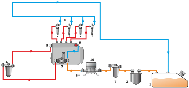
Differential flow meter installation “On suction side”
Installation of a differential/two-chamber flow meter according to this scheme is as follows:
“On suction side” scheme
Installation of a differential flow meter as per “On suction side” scheme:
Fuel tank
Rough filter
Fine filter
Low-pressure fuel pump
High-pressure fuel pump
Injectors
Differential flow meter
Non-return valve (*recommended)
The following changes will be made to the standard fuel system
An additional fine filter is installed between the rough filter and the straight-flow measured chamber. It prevents the chamber from clogging and can function as a deaerator in such cases there is not much air in the fuel.
The return fuel line is connected with the return-flow chamber inlet via a pipe.
The chamber outlet is connected to the tank by a pipe.
Advantages:
no changes in the fuel system;
installation possible for the engine during the warranty period.
Disadvantages:
higher costs;
higher fuel consumption measurement error (up to 3%);
additional fine filter and meter increase load on the low-pressure fuel pump.
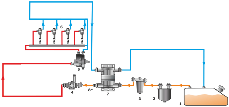
Differential flow meter installation “On pressure side”
Installation of a differential/two-chamber flow meter according to this scheme is as follows:
“On pressure side”
Installation of a differential flow meter as per “On pressure side” scheme:
Fuel tank
Rough filter
Low-pressure fuel pump
Fine filter
Differential flow meter
Injectors
High-pressure fuel pump
The following changes will be made to the standard fuel system:
The return fuel line is connected with the return-flow chamber inlet via a pipe. The chamber outlet is connected to the tank by a pipe.
The return-flow measurement chamber output is connected to the fuel tank via a pipe.
Advantages:
no changes in the fuel system;
installation possible for the engine during warranty period.
Disadvantages:
higher costs (when compared with a single-chamber installation);
higher fuel consumption measurement error;
CAN-bus flow meter installation
To install a CAN-bus flow meter, simply connect a GPS tracking device to a CAN bus and read the "Total fuel consumption" parameter. This process allows for efficient monitoring and management of fuel consumption.
To establish a connection with a CAN-bus, the first step is to locate it within your vehicle. The CAN bus typically consists of a twisted pair of wires intertwined together. In order to pinpoint the specific location of the CAN bus amidst the intricate web of car wires, it is advisable to refer to the wiring diagrams.
Once you have successfully identified the CAN bus, there are two options to establish a connection: either through a CAN Crocodile contactless reader (recommended for its non-destructive nature) or by directly connecting to it (less preferable).
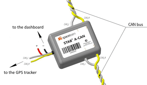
CAN-bus flow meter connection
General procedure for connecting to the CAN bus:
First, you need to know the brand, model and year of manufacture of the car to which you want to connect a CAN-bus.
Later, by looking at this table, check whether the full fuel consumption parameter is transmitted to the CAN-bus of your car. If the data is not transmitted, this option is not possible.
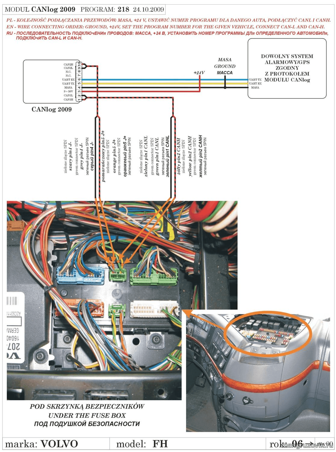
CAN-bus flow meter connection example
Go to your tracker manufacturer’s website to select a CAN module brand that fits.
For example, when connecting Teltonika trackers to passenger cars, the CAN-module LV-CAN 200 is used, and for trucks, it will be ALLCAN 300.
Ask the CAN module vendor to supply a connection diagram for your vehicle brand, model and year of manufacture. Usually it takes no more than 30 minutes to find the right diagram.
Connect the CAN module to the CAN bus according to the diagram.
Use a USB cable to connect the CAN module to the dashboard and the laptop with pre-downloaded setup software.
Launch the software for configuring the CAN module and insert the number given in the diagram to set up the CAN module.
Disconnect the CAN module from the computer and then connect it to the tracker.
The setup time is approximately 30 minutes (considering the diagram is available).
Installation of several flow meters on one vehicle
Sometimes more than one flow meter is installed on a single vehicle. This is often the case when a vehicle has two parallel fuel lines.
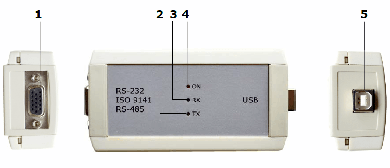
For example, one line delivers fuel to the engine that runs the car while the other transfers fuel to the engine of the compressor unit mounted on the same vehicle. To control fuel in each of the lines, it is necessary to install several flow meters. You can connect flow meters to a tracker in several ways, for example via an RS-485 interface.
How to connect a flow meter to a GPS tracker
As of 2018, the following interfaces were used to connect a flow meter to a GPS tracker:
For hardware flow meters:
Impulse interface;
Serial interfaces:
RS-232
RS-485
CAN-like
For CAN-bus flow meters:
By connecting to a CAN bus network
Analog interface
Equipment: Flow meter with an impulse output, a GPS tracker with an impulse input (for example, Wonde Proud VT350).
Specifications: From the GPS tracker to the monitoring platform, the impulse value (raw data) is transmitted in the form of equal impulses.
In order to convert impulses to liters, it is necessary to enter a special coefficient into a monitoring platform (to do it, head to the Measurement Sensor settings). The coefficient is calculated based on the number of impulses corresponding to one liter. You can find this data in your manufacturer’s guidelines. For example, for a Technoton DFM 100D flow meter, one liter corresponds to 200 impulses.
Advantages: It can be used with relatively old models of GPS trackers
Disadvantages: The impulse interface is supported on a smaller number of GPS trackers as compared to digital interfaces.
Application: Flow meters with an impulse interface are usually ordered for connecting to older trackers that have already been installed.
Digital interfaces
Equipment: Flow meter with RS-232 (or RS-485) interface, tracker with RS-232 (or RS-485) interface.
Specifications: From the GPS tracker to the monitoring platform, the impulse value (raw data) is transmitted as digital signals (human readable values without units of measurement) over wiring, all in digital form.
To convert the received values to liters, it is necessary to enter a special coefficient into the monitoring platform (to do it, head to the Measurement Sensor settings). The coefficient is calculated based on the conventional numbers corresponding to one liter. You can find this data in your manufacturer’s guidelines. For example, for a Technoton DFM 100D flow meter, one liter corresponds to 200 received units.
Advantages: Wires help to achieve an ultimate noise immunity during signal transmission. You will also be able to connect more than one sensor on one tracker (through RS-485 interface, RS-232 allows to connect only one sensor). Check the GPS tracker manufacturer’s website to see the number of fuel sensors to be connected via RS-485.
Disadvantages: Trackers with digital interfaces are usually more pricey than similar trackers without digital inputs.
Application: It is easier to find a GPS tracker with a digital interface. In practice, only one interface is required to be connected to a flow meter. Just make sure you consider whether the GPS tracker has RS-232 or RS-485 input.
CAN-like bus / S6 Interface
Equipment: A flow meter with a CAN-like interface, a CAN module for reading data from a CAN bus, a tracker compatible with a CAN module.
Specifications: Technoton, a world-famous Belarus-based manufacturer, promotes the idea of a universal interface for factory-installed and additional sensors (including flow meters). Technoton offers CAN 2.0 for this purpose. Its operating principle is the following: the raw data is first sent to the CAN bus network, then it is read by a CAN module and transferred to the monitoring platform.
In order to convert the received raw data to liters, it is necessary to enter a special coefficient into the monitoring platform. The coefficient is calculated based on the number of CAN units in one liter. You can find this data in your manufacturer’s guidelines. For example, for a Technoton DFM 100D flow meter, one liter corresponds to 200 CAN units.
Advantages: This approach yields a few benefits. Mainly it removes any limitations on the number of devices to be connected to one tracker.
Disadvantages: Fuel sensors operating on CAN interface will cost more compared to similar solutions with other outputs. That’s why this technology hasn’t become widespread.
Application: It is rarely used due to the higher cost of the flow meter. Connecting more than one flow meter in practice is seldom required.
CAN flow meter
Equipment: CAN module for CAN data reading, CAN module-compatible GPS tracker or OBD2 GPS tracker supporting OBD data reading.
Specifications: Information on the total vehicle fuel consumption is transmitted in the form of a virtual counter. The values of the counter are indicated in liters, therefore, you don't need to enter a separate coefficient into the monitoring platform.
Advantages: High data accuracy, fast non invasive installation or DIY installation in case of OBD2 tracker. No extra money spent on sensor setup.
Disadvantages: Not all cars transmit information on the total fuel consumption via a CAN-bus.
Application: The simplicity of obtaining data is positively perceived by end users and can help to organize a better accounting of fuel consumption.
Flow meter vs Fuel level sensor
To solve tasks related to fuel control, your end customers or partners can choose between a flow meter (FM) and a fuel level sensor (FLS). To help them choose, we recommend first looking at the key features:
Indicator | FLS | FM |
|---|---|---|
The amount of fuel in the tank | Yes | No |
Fuel fillings and draining | Yes | No |
Fuel consumption per time period | Yes | Yes |
Average fuel consumption for ex., l/100km | Yes | Yes |
Fuel control when driving on rough terrain | Yes. It's recommended to install two or more FLS in each tank. | Yes |
Fuel control during a long-lasting inclinations (for ex., asphalt milling machines. | Yes. It's recommended to install two or more FLS in each tank. | Yes |
Interfaces for connection with a GPS tracker | Analog, Frequency, RS-232, RS-485, CAN | Impulse, RS-232, RS-485, CAN |
Changes to the fuel line | Not required | Required. Changes to fuel system are required in some cases |
Calibration | Required | Not required |
Installation time | 4 hrs approx. | from 4 hrs to several days |
Equipment price | from 46 to 155 US$ | from 232 to 697 US$ |
To summarize:
Fuel level sensors are cheaper and easier to install
FLS allows to control more parameters
Flow meters only allow you to keep records on the fuel that has been consumed. In case you need to detect fuel thefts, it is required to know the amount of fuel in the tank at the beginning and at the end of the period (for this purpose, installing a flow meter is not enough).
Therefore, we recommend to use a flow meter only in cases when a fuel level sensor cannot be implemented.